


This post describes how to make a robot which is controlled using the EyesBot Driver iOS app, which is free and in the app store. The robot can be made in 3 hours or so if you have all the parts and you are good with a soldering iron. The cost for parts is about US$60.00, but will vary according to the cost of parts in your location. A sketch for the Arduino Pro Mini is also included.
Notice: This post involves working with electronic components, soldering, and your iOS device. If you injure yourself or someone else, start a fire, damage or destroy your iOS device or anything else, you are responsible. We take no responsibility for your use of the information contained in this blog, you use this information at your own risk.
You can see a demo of the robot and a discussion of how to create the robot in this video. It follows the steps discussed below, and the shopping list referred to in the video is below in the materials section.
Materials
The following is the parts list and links to suppliers. These are all US based suppliers, but I generally order from them and I live outside the US, so they may work for you wherever you are based.
| Item Name | Number | Unit Price | Source |
| Protoboard | 1 | $4.49 | Mouser |
| Small Switch | 1 | $0.75 | Sparkfun |
| TIP 120 Transistors | 8 | $0.47 | Mouser |
| 1N4004 Diodes | 8 | $0.09 | Mouser |
| 1K Ohm Resistors | 9 | $0.07 | Mouser |
| 10K Ohm Resistors | 8 | $0.09 | Mouser |
| Phototransistors | 8 | $0.14 | Mouser |
| 1 uF Ceramic Capacitors | 2 | $0.24 | Mouser |
| 2N3904 Transistor | 1 | $0.10 | Mouser |
| White LEDs | 2 | $0.30 | Mouser |
| Arduino Pro Mini | 1 | $9.95 | Sparkfun |
| Caster | 1 | $1.99 | RobotShop |
| Wheels | 2 | $3.09 | RobotShop |
| Gear Motors | 2 | $5.58 | RobotShop |
| Headers-Female Component Sockets | 2 | $1.48 | Mouser |
| Headers-Female | 1 | $5.00 | Sparkfun |
| Headers-Male | 1 | $5.00 | Mouser |
The above assumes you have certain basic supplies like solder, soldering iron, hookup wire and batteries. If you don't have hookup wire, there is a good set at Sparkfun and here is also some solder to look at if you need solder. Also, note the headers, I use two headers for the structure that holds the Arduino Pro Mini, one type I like since they are easy to break apart and solder nicely, the other type add the necessary height and accept the leads I solder onto the Arduino.
For a power supply, you can use from 6V to 7.4V. I've tried this with 4 alkaline batteries and a 7.4V lipo and, other than the lipo being faster, they were pretty similar.
With regard to resistor values chosen, the correct resistor values for the LED headlights are at 6V or at 7.4V are 100 Ohms (93.3 calculated) and 150 Ohms (140 calcualated) based on the datasheets. I used a higher value since the lights are really bright, and higher values lead to lower energy consumption and longer component life (neither of which is really significant in this case, so if you want brighter lights, use the calculated values). For the base resistors using the formula Rb=(VPin - Vbe)/Ib and the values from the datasheets and a collector current up to 3A, the calculated value is 833 Ohm, so 1K Ohm is close enough in this case. For the 2N2904, the calculated value was also in the ballpark of 1K, so this is also close enough. The correct values leading to the TIP120s and 2N3904 don't vary with supply voltage since the base resistors are connected to the 5V regulated output from the Arduino digital ouput pin.
Process for stuffing and soldering the board
This is the process that I follow and it takes me about 3 hours to do the cutting and soldering. If this is your first time, you may end up desoldering and resoldering and basically having some difficulty, so you may require several sessions, possibly frustrating, over a few days.
Step 1, Put everything together
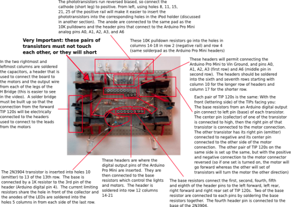
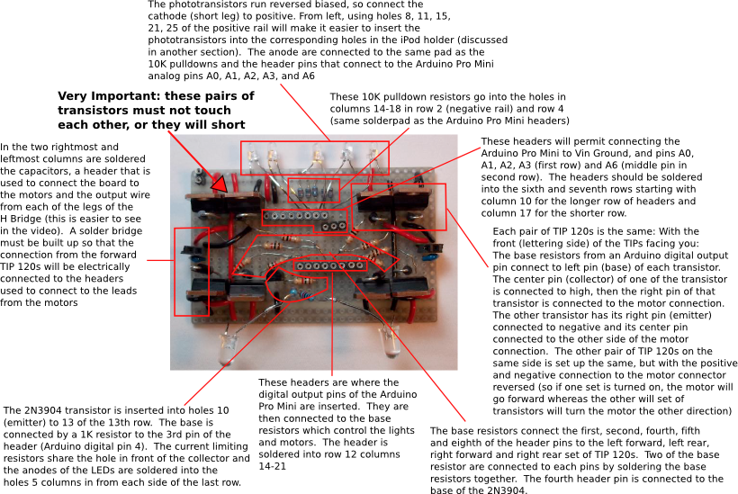
The following shows all of the parts inserted into the board after they are soldered into place. The guide may be useful for where to place everything. I've soldered in components in the wrong spot several times and the rework slows everything down and results in a less aesthetic board, so it is definitely worth checking twice.
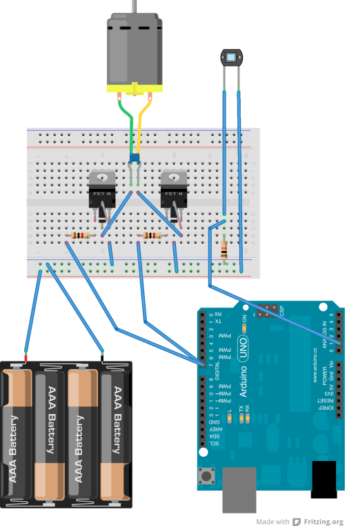
The following schematic shows one "quadrant". That is, the connection of a phototransistor to one of the analog input pins and half of one of the H-Bridges. Its quick to put this together on a breadboard and worth the time as it will make it easier to see how the protoboard should be set up. The transistors labeled "FET N" are the TIP 120s. Also the power supply for the arduino isn't shown, if you are using a 9V battery, you can hook high and low from the breadboard to Vin and ground on the Arduino.
More fun
Please continue on to part two where the soldering and robot building is done
 Computer vision
Artificial intelligence
Effecting the physical world
Our robot controller app is available in the app store and will be be available soon for Android
