This post continues from part one, which contains the parts list and a diagram
Step 2, Solder in resistors, wires, headers, and caps
After putting everything in place, I pull out the diodes and transistors (the 4 TIP120s and the 2N3904) and then solder in the resistors, wires, headers and capacitors. I typically cover the components with a sponge when I turn them over to keep everything in place, plus then I have a conveniently located sponge to clean the soldering iron tip with.
The wire lengths that I used for the jumpers were:
| Wire Color | Number | Length | Purpose |
| Red | 1 | 5.5cm | Positive to positive rail jumper |
| Black | 1 | 5.0cm | Negative rail to negative rail jumper |
| Red | 5 | 2.0cm | 4 Positive rail to TIP 120 jumpers, one for positive rail to Arduino raw Vin |
| Black | 6 | 2.0cm | 4 Negative rail to TIP 120 jumpers, 1 for negative rail to Arduino ground, 1 for 2N3904 transistor emitter pin to ground |
| Red | 4 | 3cm | Jumpers from TIP 120 to motor connection |
| Black | 4 | 3cm | Jumpers from TIP 120 to motor connection |
In all cases I stripped about 4mm of insulation from the end for soldering. Also, this doesn't include the wires to the battery or the motors, the length of which will depend on how you configure your robot.
Step 3, Solder in transistors and diodes
Next step is the transistors and diodes. The TIP120s have heat sinks, so they are somewhat difficult to solder, but after this step, the vast majority of the soldering is done.
Step 4, iPod holder
In this step, you will make a container to hold the iPod on which you'll be running EyesBot Driver.
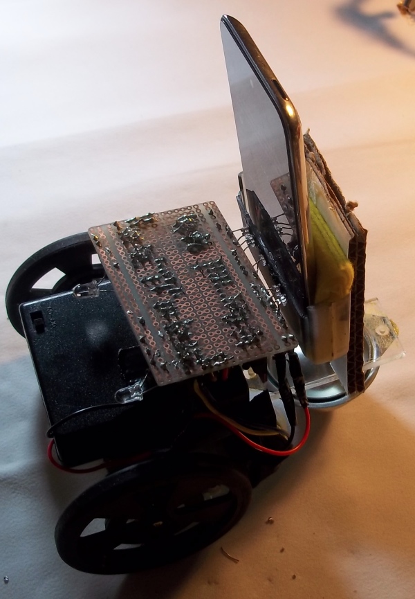
I repurposed a plastic container for the robot that I am building for this demo. The only thing that is critical for the container is that it can hold an iPod and that the phototransistors are adjacent to the correct region of the iPod screen. In the image above the phototransistors are jutting into holes in the iPod holder that correspond with the black square on the interface shown below.
Step 5, Solder in headlight LEDs, current limiting resistors for LEDs, and phototransistors
The last items to solder in are the LEDs and their resistors plus the phototransistors. Refer to the photo under step 7 to see the end result.
Step 6, Cleaning, inspection, and testing
In this step you should wash your board and carefully inspect all the solder joints and the spaces between the pads for unwanted solder bridges.
Step 7, Add Arduino
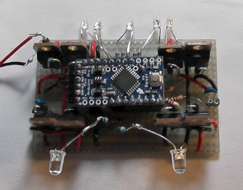
First, you will need to upload a sketch to to the Arduino Pro Mini.
If all looks well, you can connect the motors to the motor connectors and a power source, then test.
The board with Arduino Pro Mini in place should look like:
Step 8, Robot body
You can be quite creative here, all you need is a light, stiff object for the body. In the video that accompanies this post, I used some cardboard and scrap plastic (a photo is shown under step 4, above). The robot is 2 wheel drive, so you will likely need a caster for a third point of contact with the ground. Also, you need a place to place your power supply and the iPod need an unobstructed forward view.
Step 9, Using
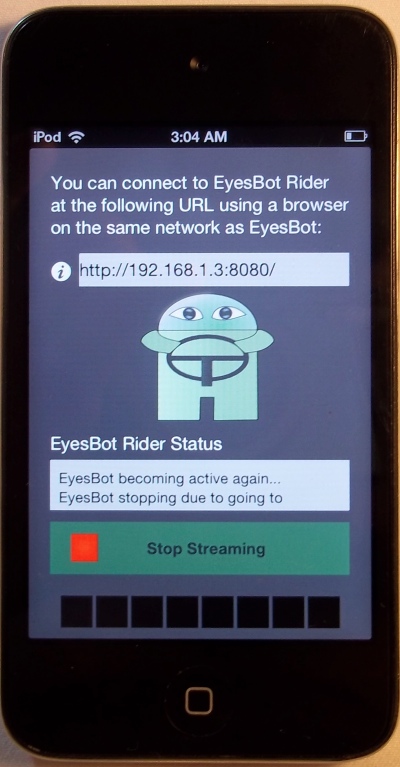
Finally, you can use your robot. Its best to see the video so that you can get an idea about how to use the app, but basically, you load EyesBot Driver on your iOS device, start the app, then click the "Start Streaming" button.
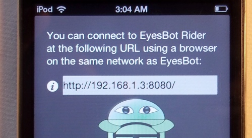
The streaming interface has an IP address which you type into your browser location field and
you will then see the browser interface for EyesBot Driver
When the app is streaming, slide it into the iPod holder you created and you should then be able to control your robot using the web interface.
More fun
Upsoni is working on object recognition,
distance finding, using the robot with web services and
exploring way to open up EyesBot Driver to permit end users to incorporate their own code. If you
want to contact Upsoni, the creator of EyesBot Driver, place send an email to John Keogh at

 Computer vision
Artificial intelligence
Effecting the physical world
Our robot controller app is available in the app store and will be be available soon for Android